Over the past year I've activated a few SOTA summits with nothing more than a handheld and the stock antenna supplied. I have also looked at a couple of options to improve performance and keep weight and bulk down to a minimum.
The first thing I tried was a pigtail wire. This is simply a ¼ wave length of wire with a lug at one end that simply screws down on the SMA connector between the antenna and the radio and acts as a counterpoise for improved performance. Playing around with one of these does make a marginal difference and might be enough to get the contact logged where you would otherwise fail.
One of the other things I've tried is to unscrew the ground independent dual band whip from the vehicle take it to the summit sticking out of the backpack. A 5 metre length of coax with a BNC and base socket for the antenna is the connecttion for the radio and are the main parts of this setup. At the transmitting site, a string can be tied to the tip of the antenna and thrown over a tree limb to hoist it up a few metres. The antenna can also be taped to a squid pole or other support. This setup is versatile and light and takes up the least amount of room and is ideal for HT only activations with the only disadvantage being the length of the whip sticking out of the backpack being a nuisance when traversing through thick bush. A setup like this will almost certainly allow you to qualify summits within striking range of urban areas quickly without the need to mess around setting up radios, batteries and bulky antennas for other bands.
I've also tried a 2 metre J-pole antenna made from 300 ohm TV ribbon which is wonderfully light and compact but the biggest problem has been reliability. The wire is so fine that it it quickly breaks usually at the most inconvenient time.
Something that caught my eye recently was the SOTABEAMS 2 metre MFD ( Multi Function Dipole). I like the idea of a complete self supporting antenna such as the vertical HF antenna I frequently use on SOTA activations as it packs completely within the backpack without the need for an additional tuner or bulky squid pole. The MFD promises reasonable performance with the flexibility to mount the dipole section vertically for FM or horizontally for SSB operation. To buy the kit from SOTABEAMS in the UK would cost around $55 with the optional goody bag consisting of some nylon rope, 3 ground pegs and a couple of velcro straps. Another option is a ground spike at an additional cost. Fair enough but looking at pictures and a youtube video of the antenna, I decided that I would build one myself as I had all the other ingredients except the 20mm electrical conduit, T-connector and couplings.
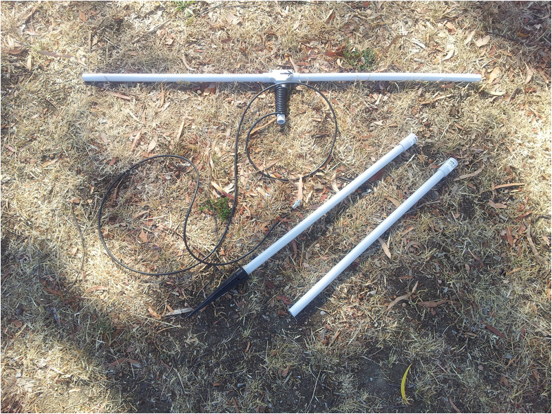
The MRG MFD with the pole sections and spike
A quick trip down to Bunnings and a short time later I had a 4 metre length of conduit and the other bits for under $5.
The ingredients for MRG MFD antenna as constructed:
3.5 metres RG58/U
1 x BNC connector
1030mm insulated copper strand wire
1 x twin terminal block
1 x small cable tie
4 x 510mm lengths 20mm pvc conduit
1 x 110mm length 20mm pvc conduit
2 x 20mm conduit couplings
1 x 20mm T-connector with inspection cover
Optional parts to complete the antenna:
3 x 2.5m nylon rope
3 x tent pegs
A ground spike of some description is worthwhile. I happened to have an unused aluminium spike from a low voltage garden light which the conduit screwed into perfectly. The spike also has a cover made from an offcut of conduit to protect the spike from damaging anything in transit.
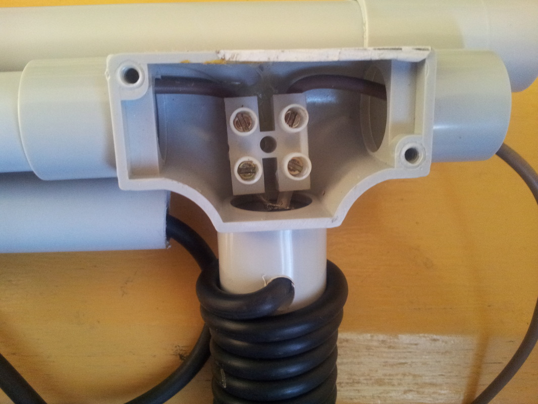
Putting the antenna together is simple enough. Cut the conduit lengths as described. The wire I used for the dipole was striped out of an old extension cord. Cut the 1030mm wire into 2 x ¼ wavelengths for the dipole. These will be trimmed to SWR later. Strip the insulation on one end of the wires and screw into the terminal connector. Push the 110mm conduit firmly into the bottom of the T-connector and carefully drill a hole and feed the RG58/U into the connector. Strip back the coax and terminate the braid to one side of the terminal block and the centre lead to the other. Get your glue gun and melt a big blob of glue onto the back of the terminal block and quickly position it centrally inside the T-connector before it sets. Gently pulling the coax back through the drilled hole will help position the terminal block before the glue sets. Feed the dipole wires out each side of the T-connector and then tightly wrap 15 turns of the coax around the conduit to form a choke balun. Drill 2 small holes in the conduit adjacent to the last turn of coax and install the cable tie to hold the choke balun in place. Terminate the end of the coax with a BNC or other connector to suit your radio. The choke balun consumes almost one metre of the coax and the remaining 2.5 metres or so is ample for most portable setups.
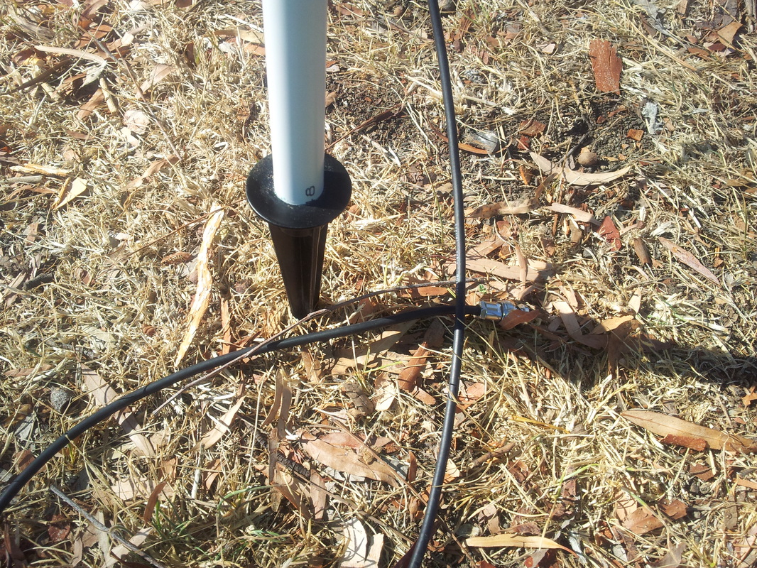 A spike from a low voltage garden light fits perfectly | 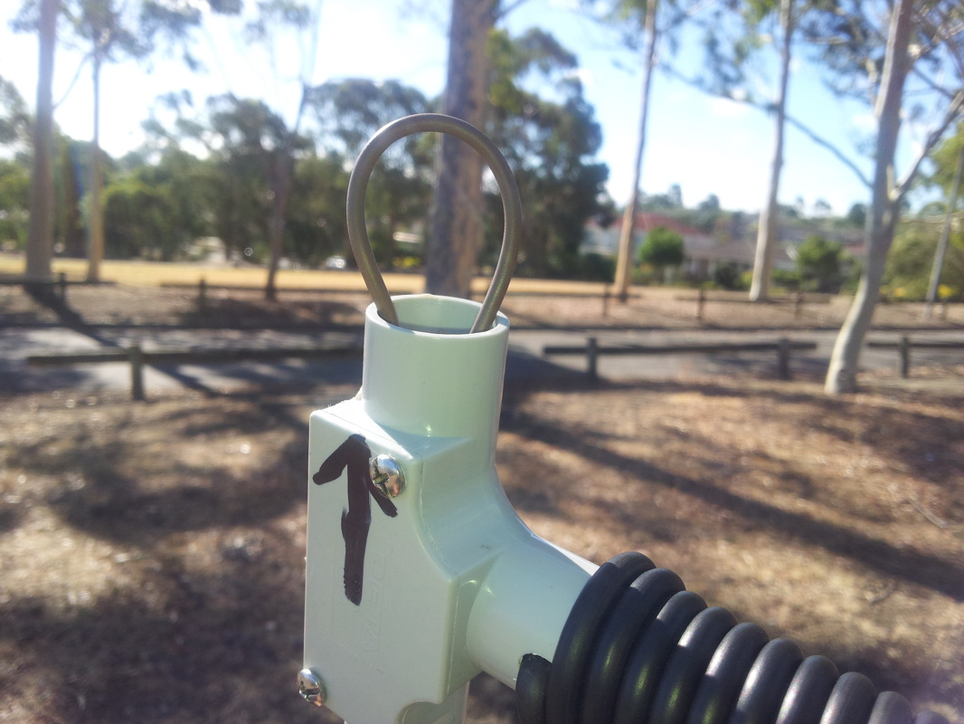 Feed one side of the dipole wire back through the centre for storage or transporting |
Next assemble the antenna. Erect the two lower pole sections using the couplings and either strap it to a vertical support or spike it like mine. There should be at least 10mm of conduit at the end of your choke balun to push into the vertical section. Feed the dipole wires through the other two conduit sections and push into the T-connector. Congratulations. You now have a horizontal dipole for 2 metres. The next thing to do is SWR the antenna. I tuned my antenna for the middle of the band at 146.000 Mhz. The easiest way to cut the dipole is to pull the dipole tubes out and cut the wires together side by side. Reassemble the supporting tubes and test the SWR again. Continue as many times as required to tune the antenna but take it easy. Cut no more than 2mm at a time when the SWR gets down around 1:5 to 1 or you may take too much off.
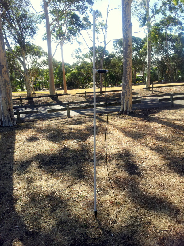 | Once tuned, a quck test with the multimeter just to detemine which leg of the dipole is connected to the centre of the coax. Mark an arrow in the T-connector so when the antenna is used vertically, this side of the dipole will be at the top. When disassembled the conduit in the “hot” side of the antenna is pulled apart and the wire is simply fed back through the T-connector for storage. Be sure to leave a little loop near the end so it can easily be pulled out when assembling the antenna. To test the antenna in field conditions I went down to the local park. I first set it up vertically. It was a reasonably windy afternoon and the antenna waved around a fair bit so I guyed it out with three lengths of light nylon rope with a loop in each end. With the antenna steadied I checked the SWR once again which hadn't changed from the initial tuning at all. I set up the FT-817 and tested out the antenna on a number of repeaters and was easily able to hit all of them that I could normaly do with a handheld. Next I put out a call on 146.500 FM and straight away got a response from Tony VK3CAT at his QTH, a distance of around 17 km. Not too bad with 5 watts across the suburbs. |
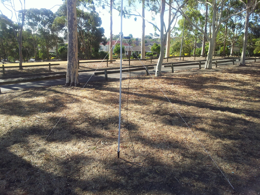 The antenna guyed in vertical position | 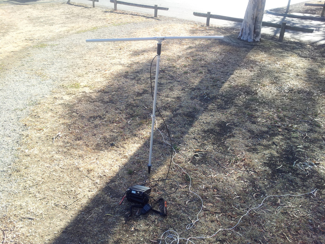 The antenna set up in horizontal position |
The next test was to set up the antenna horizontally and try SSB. It only took a minute to configure the antenna set up roughly broadside to Tony's position. This time I didn't really need to guy it despite the wind. Even though the antenna was little more than a metre parallel to the ground I received a good report once again from Tony and we also experimented moving the antenna end on where my signal remained perfectly readable despite dropping 2 or 3 S points. No real match for a 5 element yagi mounted a couple of metres higher but good enough for a SOTA peak without too much extra weight to lug around. It should prove to be a fairly reliable and robust antenna.
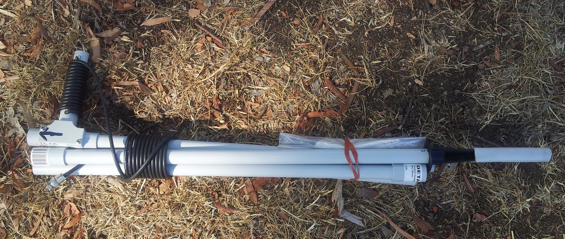
The packed down size is still a little bulky for a small backpack but manageable.
The packed down size is still a little bulky for a small backpack but manageable.
